Discussion
Ugly Construction (or ground-plane construction) is the process of using either double or single sided copper clad PC board material ( copper side up for single sided PC board ) to build electronic circuits on. Component leads that require grounding are soldered directly to the copper surface. The copper surface serves as a low impedance ground and a mechanical anchor to components soldered to it. The grounded components serve as mechanical supports for the rest of the circuitry as you build from your schematic.
If additional support is needed for components that do not connect to a grounded component, high value resistors ( 1.1 M or greater ) or terminal strips can be soldered to the copper surface and used as standoffs.
IC's or commercial diode ring mixers can be flipped upside down and leads that need grounding are soldered directly to or via small wires to the copper surface. I have found that non-stranded (solid core) wire such as the 22 AWG 3-color package sold by Radio Shack to be a good choice for hook up wire. With non-stranded wire, you do not have to worry about little stay wire hairs causing shorts and it is easier to wrap around components such as resistors or transistors. I use red for wires that carry positive voltage, green for grounding and black for wires that carry AC signals short distances. In addition, RG-174 or shielded wire is used to carry AC signals for distances of greater than 4 inches and for key components such as connecting local oscillators or RF filters which need 50 ohm impedances.
Ugly construction allows the experimenter total control over the design of a project and can be a time and money saver as well. A superior ground plane is often a side benefit. The greatest benefit in my view is construction speed. A great reference for this type of construction is The "Ugly Weekender" by Roger Hayward, KA7EXM and Wes Hayward, W7ZOI published in the August 1981 QST.
Even Ugly Construction ( some times called dead bug construction ) has its variations and lately Manhatten Style Construction technique has become very popular with some of the QRP clubs such as the NorCal QRP club. Manhatten or "paddy board" style uses small square pads cut from PC board which are glued copper side up on a large copper ground plane PC Board which is also copper side up. Basically this is taking Ugly Construction to another level as it uses the large surface ground plane of Ugly Construction and places small islands of copper PC board on top for anchoring non-grounded components. Another interesting variant is used by Dick Pattinson, VE7GC. The circuit board is placed copper side up and holes are drilled and countersunk so that the holes are isolated from the ground plane. Ungrounded components are connected underneath the main board through the countersunk holes. There are many such variations. Each Ugly Construction variant has its own advantages and disadvantages.
In yet another variation, lines can be cut into the copper board with a small hobby-cutting tool to make a few or many isolated areas for ungrounded connections, or for example an area to provide a path the for the positive supply voltage to various stages contained on the PC board.
In addition, I often use the motor tool to grind off the copper underneath VFO torroidal inductors so that the inductor Q is not effected by the being glued onto a copper surface. In audio projects, I may grind off the copper around thr PC Board mounting bolts so that the mounting bolts do not provide multiple grounds of the large PC board and create potential ground loops.
It is best to use single-sided circuit board for building VFOs onto, however double sided boards can be used as ground planes, soldered together to form a chassis, walled dividers or complete enclosures. For this type of work, I generally use a soldering iron in the 75-100 watt range. Be careful to ventilate your room as the solder and flux fumes can be harmful.
Whatever variant of Ugly Construction you use, it is sure to be a winner!
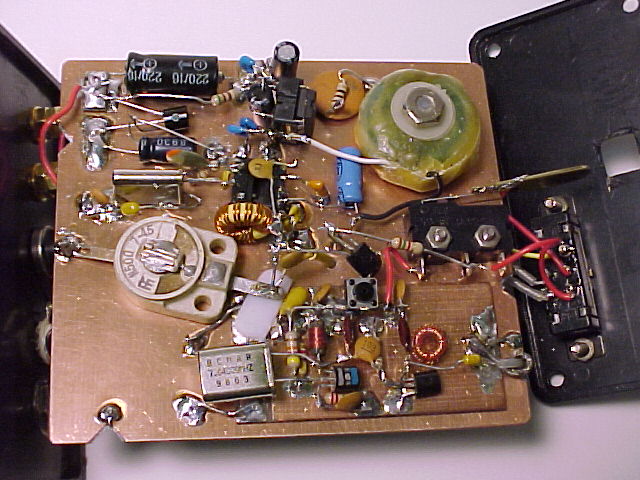
Shown below is an ugly project by Jim, WA6OTP. It is his WA6OTP Trail Radio described on his site. Check out Jim's web page at http://www.wa6otp.com/
His Pixie 2 Ugly construction photo is excellent and can be found at http://www.wa6otp.com/pixie.htm
Note how shiny the copper surface is. This can be achieved by buffing the copper PC board with steel wool before beginning construction.
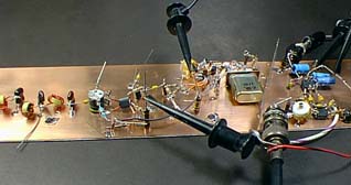
Below is a W7ZOI creation. Wes had a QSO with this rig as shown!
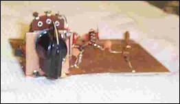
Shown below is an experimental VFO board using a pot and a rectifier diode as the variable capacitance. It was discarded as it had poor short-term drift characteristics.
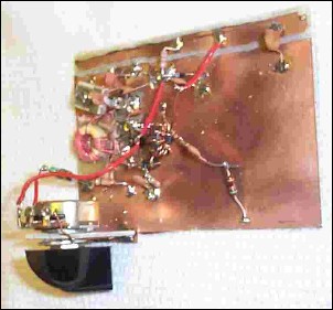
Another experimental VXO board. Small islands were cut with a hobby tool for some of the non-grounded components to aid in minaturization.

G4WIF invented a special tool for drilling pads in "Ugly" PCB material
Web page last revised Dec 28, 2002.