SHORTWAVE RECEIVER
10 kHz - 30 MHz
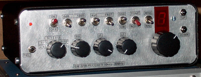
The simple shortwave receiver for CW and SSB.
SSB and CW receiver 10 kHz to 30 MHz
This receiver was made with
use of the experiences of my first receiver. This new one has some improvements
and modifications:
- It is much smaller, it is only 1/4 of the size of the old one.
- The VFO stabilisation circuit has been improved.
- The mixer and BFO have been simplified, simple readily available parts are
used for it.
- The frequency counter with extra mixer for the BFO and VFO is replaced by
one with programmable IF offset.
Enough ideas to justify the
construction of a new receiver!
No AM reception
The receiver does not have AM reception. But if you
want, you can receive AM in SSB mode. The advantage is that there is no
distortion due to selective fading.
Speech sounds acceptable, just like SSB,
music sounds like an old 78 rpm gramophone...
Block diagram.
big diagram
Description
The receiver has a 36 MHz IF with a 5 pole ladder
filter and an almost drift-free VFO, it has Xtal stability, tuning is very
comfortable.
The BFO frequency for a ladder filter should always be higher
than the IF frequency, due to the asymmetric shape of that filter. To be able to
listen to LSB signals below 10 MHz, the VFO runs from 36 - 10 MHz to 36 + 30
MHz. For LSB, the VFO frequency is below the IF frequency. So there is no USB
LSB switch!
The AVC is derived from the audio.
At the input of the
receiver is a RF attenuator and preselector.
For the frequency display, one 7
segment display is used. (see the page about a Simple frequency counter with one
7 segments led display).
The VFO
The VFO.
big diagram
The VFO
The same type of VFO is used in the "MyTRX"
transceiver.
Many small tuning ranges (23.6 kHz at 10 kHz and 52 kHz at 30
MHz) can be tuned by the 10 turn potmeter. Press the up/down switches to go to
the nearest next small tuning range. For large frequency changes, set S1 to
coarse tuning. Otherwise you have to press the up switch 1000 times to go from
10 kHz to 30 MHz!!
The system is based on a frequency locking system with a
sampler with a VCO (Voltage Controlled Oscillator) and a VXO (Variable Xtal
Oscillator). Harmonics of the (VCO/16384) are locked to the VXO. The VCO runs
from 26 to 66 MHz and the VXO frequency is 8867 kHz. Frequency variation of the
VXO is 7 kHz. If you want to calculate the tuning range, the formula is:
(VCO frequency) x (frequency variation of the VXO) / (VXO
frequency)
So the range of the actual small frequency band that can be tuned
by the 10 turn potentiometer is depending on the VCO frequency and the frequency
variation of the VXO.
No ceramic resonator is used in the VXO as is in the
"MyTRX" transceiver but a Xtal for better stability. Stability with a ceramic
resonator is not sufficient for this design. In the MyTRX the VCO frequency is
divided, giving better stability of the final frequency.
As the tuning range
of the VXO is less than that with a ceramic resonator, the VCO frequency is
divided by 16384 instead of 4096. The maximum frequency (here 4028 Hz) has to be
less than the 7 kHz frequency variation of the VXO. Due to another division
ratio, the loop filter component values are adjusted experimental (higher R and
C). Adjustment of the loop potentiometers is possible with an oscilloscope at
TP2, but you can do that even better with your ears. Tune to a strong carrier at
a low VCO frequency and adjust the 100 ohm potentiometer by ear for the best
distortion free audio tone. Even very small instabilities in the loop that are
not noticed with the oscilloscope are heard by ear when tuning to a strong
signal.
Up-down switches.
One important remark about that: The Up switch
does only work properly if the VXO is tuned to a high frequency. For the lower
VCO frequencies it works already when the VXO is tuned to its center frequency.
And for the Down switch it is just the opposite.
Sometimes a (not very
stable) locking occurs while there is an AC ripple on the loop (check with an
oscilloscope on TP2). But you can solve this problem with some DC offset, adjust
the 10k potentiometer a little to get this DC offset.
The HF part
The RF part.
big diagram
Attenuator, preselector and HF preamplifier
The attenuator
improves the reception considerably in the evening on the 40 and 30 meter band
while the sensitivity is still good enough to receive weak stations. The
low-pass filter suppresses the mirror frequencies and the 36 MHz IF frequency. A
trimmer is added for extra suppression of 36 MHz signals received via the
antenna.
Instead of broadband input filters, a tuned selective preselector is
applied to improve the performance of the receiver considerably. The inductances
are readily available parts and mounted directly on the bandswitch. For the band
below 150 kHz there is a simple RC low pass filter.
The HF amplifier is
certainly not a top performance transistor amplifier, but good enough due to the
selective preselector. The first transistor is an impedance match, the second
one gives some extra gain. The gain can be varied by changing the 220 ohm
emitter resistor.
The mixer
The mixer is a balanced transistor mixer, not because
that it is so good, but because I was curious to see if it is really as bad as
they say. Well, it's performance is acceptable together with the preselector and
input attenuator.
It is single balanced. A double balanced mixer will also
attenuate 36 MHz signals from the antenna and noise on that frequency generated
by the RF preamplifier. That will improve the sensitivity at 28 MHz. Another
advantage of such mixers are a better buffering of the VFO signal. I had to add
a resistor of 820 ohm between the RF preamplifier and the mixer to avoid that
the VFO frequency changes when extremely strong signals (more than 0 dBm) were
fed to the antenna input. My advice: Take a NE612 or even a SL6440 if you want
to have a real good mixer, do not copy this one.
The IF and BFO
A 5 pole IF ladder filter (2 kHz wide) is followed
by a Poljakov mixer with two diodes. The BFO frequency for such a mixer is half
it's working frequency (half the IF frequency: 18 MHz). The advantage is that it
is easy to make a VXO for 18 MHz but not for 36 MHz as you need an overtone
crystal for that frequency. It is not possible to make a good VXO with an
overtone oscillator.
The IF gain control is not really an IF control as it is
in the LF part of the receiver. But it has the same effect: Control the AVC
voltage.
The AF part
The audio part.
big diagram
The
Audio part
At the input is a second SSB audio filter for extra
selectivity and high frequency audio noise suppression. It is followed by a CW
filter (600 Hz high pass and 800 Hz low pass).
The AVC is controlled by a fet
in the LF part of the receiver. It is also used for mute during TX. Even a side
tone oscillator is included, so that the receiver can be used with a
transmitter.
The Frequency counter
The Frequency Counter.
big diagram
The Frequency counter
Similar to that used in the "MyTRX"
transceiver (see also the page about a Simple frequency counter with one 7
segments led display if you want to know how you can read the frequency while
using only one display). There is an extra input to measure the frequency of the
external transmitter. If a DC voltage is applied together with the RF signal,
the counter measures the frequency of the transmitter. This DC signal is
switched by the tune switch of the external transmitter.
The exact IF
frequency is programmed by zero beating the VFO at 36 MHz (0 Hz reception
frequency). This value is stored in the internal eeprom.
Results
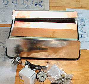
The start of the Barefoot Technology
receiver project.
Only some ideas, drawings and components. Should it ever
work?
It works! Although not as good as an expensive commercial
receiver, a lot of DX is heard on all amateur bands. Selectivity and sensitivity
are good. Tuning is very comfortable. CW and SSB filter are okay. AVC works
good.
As the mixer is not a very good one, I have to use the input attenuator
in the evening at 40 and 30 meter. But also with the extra input attenuator,
sensitivity is good enough to hear the atmospheric noise.
Even with 20 dB
attenuation, the sensitivity on 30 and 40 meter is sufficient. The advantage is
that the 3rd IP also increases with the attenuator value.
A lot of hours are
already spend to listen to this receiver with pleasure. Even to AM
transmissions! The receiver is stable and the CW filter sounds good, not too
narrow. Operation is simple, no manual needed for all kinds of "hidden"
controls.
Of course there was an error: the 56k and 10k resistors of the
under-voltage circuit of the frequency counter were exchanged (diagram is
correct, not the photo of the frequency counter). The result was that the EEprom
values changed sometimes during switching off the receiver.
SOFTWARE FOR THE FREQUENCY
COUNTER
"FREQRX02.ZIP"
WITH "FREQRX02.ASM" TO PROGRAM THE FREQUENCY COUNTER
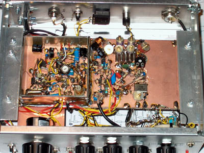
PHOTOGRAPHS OF THE RECEIVER
CONSTRUCTION
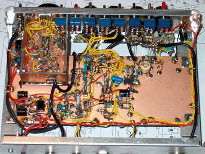
Top view of the interior of the receiver.
Bottom view of the interior of the receiver.
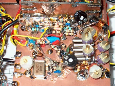
RF preamplifier, mixer with trifilair coil on plastic
rod (no ferrite!)
ladder filter, BFO with Poljakov mixer, LF preamplifier
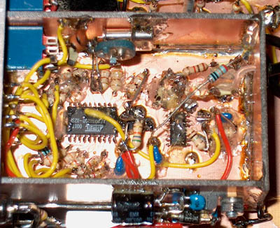
The frequency counter with SMD chips.
Thin wires
are soldered to the pins of the chips before mounting them.
During soldering
such a thin wire, the pin is isolated from the others by aluminium foil.
The
SMD chips are glued on a piece of wood (from a match) on the PCB.
Pieces of a
glue stick are used to fix the resistors etc. (melting them with the soldering
iron).
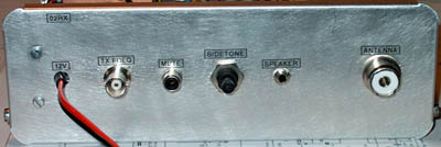
Back side of the receiver
NOTES FOR ALIGNMENT
Adjust the
trimmer of the 36 MHz reject filter for maximum attenuation of a 36 MHz signal
when the receiver is tuned to the 10 meter band.
Adjust the 100 ohm
potentiometer of the mixer for minimum noise for reception below 100
kHz.
Adjustment of the ladder filter is more complex. Input and output
trimmers are tuned to maximum signal.
The four other trimmers (30-40 pF? I do
not know) are set to 50 percent of their value. The AVC is switched off, the
audio output from the loudspeaker is connected to the audio line input of the PC
soundcard VIA A RESISTOR of 10k ohm.
An audio spectrum analyzer program is
running on the PC.
While tuning around the 10 MHz clock signal of the
frequency counter (or another carrier), see how the level varies when the tone
height changes. Adjust the trimmers for best filter shape. At each audio
frequency that has to be adjusted, find out which trimmer has most
influence.
Well after two hours I had a shape that was a little optimized for
CW and that had a quite good sideband suppression. It's performance is very
acceptable!
Do not forget to adjust the BFO frequency of 18 MHz to the filter
edge!
MEASUREMENT DATA
BACK TO INDEX PA2OHH