
Very simple minimum performance CW rig for portable outdoors activities.
"HIS TRX"
A two band 1 chip + 1
transistor
1 watt QRP CW transceiver
Very simple minimum performance CW rig for portable
outdoors activities.
Is this your rig?
If you do like extreme simplicity then you do
have the right mentality for this simple rig! Otherwise I would advice you to
make a better one and only take a quick look at the pictures and schematic
diagram of this simple rig.

HIS trx during a portable trip in the woods.
And now the serious part
Very simple rig for portable use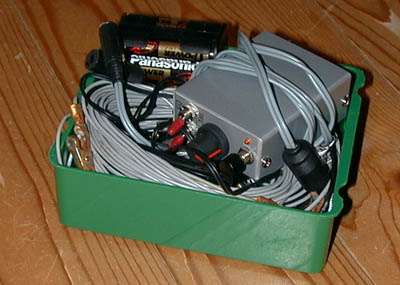
The whole portable station in a lunchbox, everything fits in
it!
The design
This is a real minimum radio amateur technology QRP
design, simple and non-professional.
One evening I tried if it is possible to
use a C-MOS switch (1/4 of a 74HC4066) as an amplifier, just like a transistor.
After a few hour's fight with oscillating circuits, I suddenly found out how to
do that. Two capacitors with good RF performance are required for stable
operation of the "74HC4066 C-MOS switch transistor". See for details the
schematic diagram given below. Of course it is not a perfect amplifier, it is
quite noisy, so the sensitivity of the receiver is only 3 uV. That is good
enough for 7 MHz and 10 MHz, but not for the higher bands. I wanted to make it
really simple, 1 transistor and 1 chip, but not too extreme. The LF output power
should be sufficient to give perfect readable signals with a walkman headset.
But there is no side tone oscillator and no volume control. The key is a simple
pushbutton at the front of the transceiver (see picture).
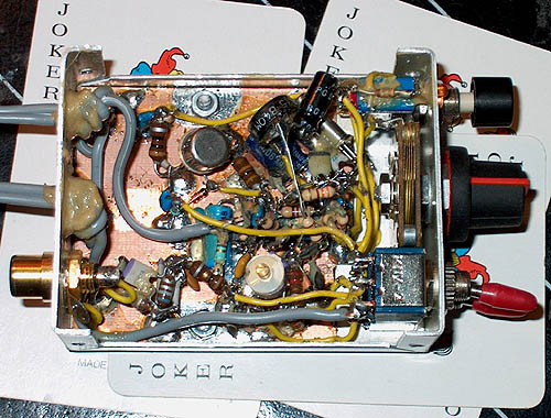
It is easy to build
the transceiver on a small single sided unetched PCB board as you can see on the
photographs.
Circuit diagram
big diagram
LF amplifier
Just two "74HC4066 C-MOS switch transistor".
It
looks as if the input resistor of the first stage is missing. But you can find
it at the input of the mixer.
If LF oscillation occurs, decrease R1. Select
R2 so that in receive mode, the supply voltage of the 74HC4066 is approximately
5 volts.
VXO
The VXO is a "C-MOS switch transistor". In transmit mode, extra
RF power is needed for the final transistor amplifier. This is obtained by the
circuit consisting of the diode 4148 and 330 ohm/100 pF. In transmit mode, the
VXO is also tuned a bit lower in frequency due to this circuit. So when you
receive a station, the VXO signal should be higher than it's frequency. Here the
values of the tuning ranges of my version:
| Crystal Frequency (kHz) |
Minimum Frequency (kHz) |
Maximum Frequency (kHz) |
| 7030.0 | 7029.5 | 7030.8 |
| 10120.0 | 10119.3 | 10121.2 |
Transmitter part
The VXO signal is amplified to 1 watt by a
transistor 2N3553.
The 1k ohm resistor makes the amplifier more stable when
mismatches occur. The 0.68 uH / 180 pF are tuned to the second harmonic of the 7
MHz transmit signal for extra suppression. One output filter is used for both 7
and 10 MHz.
Notes
Built via the ugly method (dead bug method). Parts are
soldered at one side of the print.
Inductances are commercially available
types looking like big resistors.
Do not use a HCT type but a HC type!
If
LF oscillation occurs, decrease R1.
Select the value of R2 so that in receive
mode, the supply voltage of the 74HC4066 is approximately 5 volts.
The two
earpieces of the headphone are connected in series instead of in parallel for
more audio signal.
Options
Battery indicator (led off if battery low). The 2 band
version is also given here as an option.
Performance
The receiver is quite good for large signal handling as
needed for 40 m operation in the evening. Perfect QSO's have been made, also
with a lot of QRP stations, even long chats using inverted V dipole antenna's
with the centre at 4 meters height.
Sensitivity: 3 uV signals are readable
3rd intercept: 8 dBm
Spurious
responses: Better than -90 dB
RX current: 10 mA
Transmit power: 0.5 W at 8
V; 1.5 W at 12 V
Harmonic suppression: below 30 MHz: 43 dB, above 30 MHz: 55
dB
Real simple technology....