|
Antenna Theory and Design
LPAM antennas are more difficult to construct than their
LPFM cousins. Firstly, they have to be longer. Secondly, they
have to be vertical to work well (which becomes an issue if
the antenna is longer). Thirdly, they need to have rather long
ground radials for the same reason. I will get into why
shortly, but just keep in mind that, despite your best
efforts, practicality and the constraints of your property
will severely limit the efficiency of the antenna you can
construct. If you plan on building a Part-15 station, which
limits the antenna size to 3 meters, your efficiency will be
especially low. Efficiency for Part-15 antennas is measured in
the single digits, and sometimes even less than that.
But don't read too far into this. Practical LPAM antennas,
while seemingly awful on paper, work quite well in the real
world. Lower frequency signals propagate better than higher
frequency, which almost makes up for antenna inefficiency.
Also, there are tricks to make shortened antennas perform
better.
Antenna
Theory
First, it is important to understand that frequency can be
measured in terms of physical length. To find the length of a
given frequency, use this formula:
Where W is the wavelength ( or "wave") in feet, and kHz is the broadcasting frequency.
This is important because we can use the wavelength to get an
idea of how long the antenna should be. For example, to find
out how long a wavelength for 1600kHz would be:
or "wave") in feet, and kHz is the broadcasting frequency.
This is important because we can use the wavelength to get an
idea of how long the antenna should be. For example, to find
out how long a wavelength for 1600kHz would be:
The vast majority of antennas are not made the full size of
the wavelength, however. They are usually made in fractional
sizes of the full wavelength. A 1/4-wave antenna, for example,
would be 1/4 the length of the full wavelength. Lets say you
want to make a 1/4-wave antenna. Simply multiply the fraction
into the previous equation:
So if I wanted to make a 1/4-wave antenna for 1600kHz, I
would make it 154 feet long. Similarly, we can find the
wavelength of an antenna for a given frequency if we know its
height:

Where:
A = Antenna wavelength
H = Height of antenna
(in feet)
W = Wavelength of frequency (984,000/kHz)
The (overall) optimum height for a LPAM vertical antenna
is 1/4-wave. If you can make a 1/4-wave antenna, that's
great. But unfortunately, a 1/4-wave antenna for the AM
Broadcast Band is very long and impractical for most people.
From the above formula:
As you can see, these are very long antennas! For reasons
of practicality (and for Part-15 broadcasters legality) most
people will have to settle for much shorter
antennas.
Shortened
Vertical Antennas: An Overview
Shortened vertical antennas actually consist of five
different elements. Each is a separate component that comes
together to create the antenna.
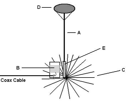
The main components are as listed:
A) Vertical Radiator
B) Loading Coil
C) Ground
Plane
D) Capacitance Hat
E) Insulator
Vertical Radiator
The vertical radiator is the element that actually radiates
the signal. It can be a thin wire, a copper pipe, irrigation
piping, or any other sort of metal conductive material (even
an existing radio tower).
Irrigation pipe is the popular choice of commercial
broadcasters. Putting up anything that bulky, however,
requires guy wires to keep it from falling, and it can be
dangerous if it is not done right. This explains the
popularity of wire antennas or smaller elements for amateur
broadcasters. One popular material for making amateur antennas
is TV mast. Make sure to have plenty of guy wires to keep the
radiator from falling, perhaps a set of three guy wires at the
top and (if needed) another set halfway down the mast. It is
suggested that you not try to make any large-diameter antennas
too tall without having more advanced knowledge of antenna
construction.
If you do use guy wires, use non-conductive ones, such as
thick nylon wire. Using conductive guy wires can cause a lot
of problems. The diameter of the vertical has to be large (and
sturdy) enough to keep it from bending. If you are just making
a 10 foot Part-15 compliant antenna, a piece of 1/2-1 inch
diameter copper piping should suffice, and it shouldn't be
necessary to have guy wires.
If you have a long tree in the broadcast area, one idea is
to string a wire antenna up using the tree as the support. To
do this, take a trout sinker and tie it to light fishing line.
Using a slingshot, shoot the sinker over a tree or other
support until you can get it to come down through the tree
(this could take a few attempts). Once that is accomplished,
tie some nylon string to the fishing line and pull the fishing
line back towards where it was shot until the string has
replaced the fishing line. Attach a wire antenna to one end of
the string, with the other part of the wire antenna attached
to an insulator or some sort of heavy weight. Pull the other
end of the string until the wire antenna is firmly in the air,
and then tie it to a nearby tree. To maximize the performance
of your radiator, make the vertical as long as you can (up to
1/4-wave). The longer the vertical is up to that point, the
better the antenna will perform.
Loading
Coil
Impedance is a complex number, related to the resistance
and reactance in a signal. It fails simple description, but
for the purposes of this guide consider it a "type" of signal,
and that in order for your antenna to work well with the
transmitter and coax cable, it must be the same impedance. If
the output impedance of a transmitter and coax cable is
50-ohms ( ),
the antenna impedance must also be 50-ohms. A shortened
antenna exhibits a high level of capacitive reactance; in
essence, it behaves like a lossy capacitor. In order to make
the antenna 50-ohms, the excess capacitive reactance needs to
be cancelled out with its electrical opposite, inductive
reactance, which is done with a loading coil. ),
the antenna impedance must also be 50-ohms. A shortened
antenna exhibits a high level of capacitive reactance; in
essence, it behaves like a lossy capacitor. In order to make
the antenna 50-ohms, the excess capacitive reactance needs to
be cancelled out with its electrical opposite, inductive
reactance, which is done with a loading coil.
A loading coil is, in all respects, a large variable
inductor that tunes the antenna's impedance to that of the
coax and/or transmitter, which is in most cases 50-ohms.
Loading coils are designed to be variable, because for amateur
broadcasters it is impossible to determine the exact impedance
value of a homemade antenna.
Loading coils are made by taking insulated wire and
wrapping it around a coil form, such as a piece of large
diameter PVC pipe. Every 10 turns or so, there is a tap that
comes out from the coil, giving you something to attach the
transmitter signal to. You then tune the coil by selecting the
tap that provides the best match for your antenna.
This method, however, only provides a coarse tuning. In
order to get the maximum amount of power out of your antenna,
you also need to be able to fine-tune the coil to the exact
point of impedance match (called resonance). To do so, either
a variable capacitor is inserted, or a variometer is
constructed. Loading Coil design is detailed later in this
guide.
Ground Plane (Counterpoise)
The counterpoise is one of the more confusing elements of
an antenna. In a nutshell, it does two things. First, it's
what the vertical portion of the antenna "pushes" off of, an
electromagnetic behavior that is required to make the antenna
actually work. The second practical function of the
counterpoise is to provide a low-resistance return for
electromagnetic current near the antenna to make up for earth
losses.
A ground plane is a type of counterpoise that consists of
radials (wires) extending horizontally from the base of a
vertical antenna in a spokes pattern. All vertical antennas
have some sort of ground plane, as all antennas require one to
work well. You need a ground plane for your antenna to
work well. The major difference with LPAM ground planes is
that they are much longer than ones for higher frequency
antennas. From the above formulas, a 1/4-wave radial for
1600kHz is 153.75 feet long.
Note that a ground plane is not the same thing as an
electrical ground (though they are often electrically
connected to ground via the return of the coax). That is to
say, you cannot just bury a grounding rod and then use that as
your "ground plane". The behavior and purpose of a ground
plane is quite different than a simple low-resistance path to
earth, though the use of the word "ground" for both elements
often makes them sound like they are related. They are not.
If you place the radials on (or bury them in) the ground,
you will have to use a lot of radials to make up for earth
losses. Commercial broadcasters use as many as 120 1/4-wave
radials for their stations, which is considered the optimal
configuration. But this is a potentially time consuming and
expensive task (at 1600kHz, you would need 18,450 feet of wire
to do this!) Like with the vertical radiator it is often
impractical to achieve an optimal ground plane, but try to
make it as good as you can. A lousy ground plane will work far
better than no ground plane at all.
One way to reduce earth loss is to place the antenna on top
of an elevated roof. If the roof happens to be metal, attach
the electrical ground to it and the roof itself will serve as
the ground plane. If the roof is not metal, placing an antenna
on it will still most likely improve range. Another benefit is
that considerably fewer radials will be needed. Elevated
antennas only typically need 4-8 radials to achieve optimal
efficiency, far less than are needed to reach the same level
with an earth-based antenna.
Here are some general rules for constructing an effective
ground plane:
Have all radials equally spaced in a circle around the
antenna. Attach each radial to a central location at the base
of the antenna, such as a pie pan or a circular loop of thick
copper wire. Make an electrical connection, such as an
alligator clip, or solder the radials to the centerpiece.
The radials should be as long as possible, keeping
property size in mind. Optimal length for radials varies with
the length of the vertical radiator, but generally the longer
the better. Don't use radials longer than 1/4-wave unless you
know what you are doing.
The more radials the better, but the gain becomes
progressively smaller. Increasing the number of radials from 4
to 16 significantly increases antenna efficiency, but after
that the gains become less radical. Increasing the number of
radials from 16 to 60 would provide less of a gain. If you are
using an elevated ground plane, you shouldn't need more than
4-8 radials.
More is better than longer. 8 radials of 1/8-wave are
better than 4 radials of 1/4-wave.
Insulated or bare wire can be used. Copper is preferred,
but aluminum can be used if the acid level of the soil is low.
Sizes can be anywhere from 5-20AWG. Go with what's cheapest.
The radials don't need to be in a perfectly straight line
from the antenna, nor do they have to be perfectly evenly
distributed. They can be bent, risen, or lowered slightly to
fit the property.
If it's not possible to make a radial system, there are a
few long-shot alternatives. One alternative is to bury a few
ground rods or several copper pipes near the base of the
antenna (eight feet into the ground), wire them together and
then use that as your ground. You could also attach the ground
to underground water pipes or a nearby faucet. It might be
better than no ground system at all, but don't expect
miracles.
Capacitance Hat
A capacitance hat is a component that helps to even the
current flow through an antenna. Without one, more of the
signal is propagated at the bottom of the vertical radiator
than at the top. If more of the signal is propagating at the
top of the antenna, the signal does a better job of getting
above trees and nearby objects. Capacitance hats also help to
increase the bandwidth of the vertical radiator, which can
lead to improved audio fidelity if the "Q" factor of the
antenna is too high.
A capacitance hat can be a large metal disk, a pie plate
with spokes of stiff copper wire extending from it, a pyramid
of wires extending a few feet from the top and attaching to
the guy wires, or simply anything metal coming out
horizontally from the top of the antenna such as several wires
stringed to insulators (anything non-conductive) on nearby
trees. Capacitance hat construction is not critical, feel free
to experiment with whatever works best for you.
Insulator
This is the base of the antenna. It has to be
non-conductive and sturdy enough to hold the antenna in place.
Avoid using concrete and wood to directly insulate the
antenna, because they can absorb water. Rubber and plastic
insulators work best. If you are using a wire antenna strung
from a tree, nylon string tied to something heavy on the
ground serves as a good support to tighten and hold the
antenna in place. If your vertical radiator is thicker than a
wire, the insulator will probably have to be
hammered/concreted into the ground for stability. Don't forget
the guy wires.
Building a Loading Coil
Four things are considered in the development of a loading
coil. First, they need to be able to coarsely vary in
inductance, which is implemented in the form of tap points in
the coil at certain intervals. Secondly, they must be able to
fine-tune to the exact level of inductance needed. Thirdly,
they need to be sturdy, which means the wires must be firmly
on the coil and the coil must be able to handle unfavorable
weather conditions. And finally, they need to have enough
inductance to properly tune the antenna. Variable loading
coils can take a little time to make (a day or two), but once
you build one you never have to do it again, even if you
change frequencies or the antenna.
There is no standard for what wire size to use, but it's a
good idea to use 20AWG or larger wire to avoid loss due to
wire resistance. The wire must be insulated when wrapped onto
a form. Plastic insulated, litz, and enamel-coated wires work
just fine. Enamel coated wire might look like bare copper at
first sight but it isn't, it tends to have a darker, redder
color than copper. Enamel coating can be removed with
sandpaper or burned off with a lighter. The coil form most
people use is a large (4 to 12 inch) diameter PVC pipe. PVC
piping can be purchased at most local hardware stores by the
foot; 2-3 feet should be all that is needed. Basically
anything that is round and doesn't cause significant RF loss
will work well, such as a plastic drinks container or an
oatmeal cylinder. If you do get PVC pipe, get the white kind.
The other kinds of PVC have different "dielectric" properties
and can be lossy at RF (though this is a bigger concern at
higher frequencies than it is at mediumwave).
How much inductance (how many turns of wire) should your
coil have? This depends on antenna length, antenna diameter,
and operating frequency. We can approximate the amount of
inductance required to tune an antenna, which is good enough
for designing a loading coil. Make sure you design the coil so
that it is somewhat larger than needed. If the coil is too
small, you won't be able to tune it without adding more
inductance, so good engineering practice calls for the design
of a loading coil that has more inductance than is needed for
the specific application.
Loading Coil Inductance Values
Frequency
(kHz)
|
Ant. Height (ft)
|
Diameter (in)
|
Inductance
Req. (uH)
|
1600
|
10
|
1/16
|
134
|
1600
|
30
|
1/16
|
86
|
1600
|
50
|
1/16
|
62
|
1600
|
10
|
1/2
|
119
|
1600
|
30
|
2
|
62
|
1300
|
10
|
1/16
|
204
|
1300
|
30
|
1/16
|
133
|
1300
|
50
|
1/16
|
97
|
1300
|
10
|
1/2
|
181
|
1300
|
30
|
2
|
95
|
1000
|
10
|
1/16
|
345
|
1000
|
30
|
1/16
|
256
|
1000
|
50
|
1/16
|
168
|
1000
|
10
|
1/2
|
305
|
1000
|
30
|
2
|
162
|
700
|
10
|
1/16
|
703
|
700
|
30
|
1/16
|
463
|
700
|
50
|
1/16
|
349
|
700
|
10
|
1/2
|
623
|
700
|
30
|
2
|
333
|
500
|
10
|
1/16
|
1379
|
500
|
30
|
1/16
|
910
|
500
|
50
|
1/16
|
689
|
500
|
10
|
1/2
|
1222
|
500
|
30
|
2
|
654
|
Once the required inductance is known, the following
formulas can be used to form the coil:

or
Where:
L = Inductance of coil in microhenrys (µH)
N =
Number of turns
D = Diameter of coil in inches (twice the
radius)
H = Length of coil in
inches
Tapping the Coil
One of the "gotchas" of loading coils is that you cannot
wrap together a large coil, sand off an up-down section of the
insulation and tap the wires as-is. It simply doesn't work,
because alligator clips cannot attach to the wire. Unless you
are designing a roller-inductor (which is usually more
difficult), you have to build taps into the coil while you are
looping the wire. The best way I have found to make taps is to
use this method:

First you drill three holes into the form every 1/2 inch or
so, moving up until the coil has several sets of holes. Then,
start wrapping the wire around the loading coil firmly, and
when you come to one of the holes, push the wire into it, and
then pull it out tightly through the center hole. Place the
wire for the next segment in the other hole and through the
center, strip off the insulation with sandpaper or a wire
stripper, and then twist and solder the two wires together.
Repeat for every hole until you have the desired maximum
inductance. The inductance can be found by applying the
inductance formula as you go along.
Another quick and dirty way that works is to simply twist
the wire at each tap point as you are wrapping the wire to the
form. After you are done, sand off the insulation from the
twisted elements and you have coil taps. This could be
difficult, because the loops might come unturned when tension
is applied to make the wire fit the form tightly. One way to
resolve this is to apply superglue or solder the twisted wire
together as with the above method. When you are looping the
wire to the form, keep applying tension to the wire, otherwise
it will loosen and the coil will deform. I have found that
applying a small amount of superglue helps to keep the wires
in place. Every tap point or so, dab some super glue near the
taps and in a few places across the looped wires. Let it dry
for a few minutes, and then continue.
Fine
Tuning Loading Coils
The coil tap method only gives a coarse tuning range. In
order to get good performance out of your antenna, you have to
be able to fine-tune to the exact point of resonance. That is,
we want to have the ability to both coarsely-tune and then
finely-tune the loading coil. The coarse tuning part (the
taps) will change the amount of inductance greatly, whereas
the fine-tuning part will allow us to change the inductance a
smaller but more precise amount. This involves either
inserting a variable capacitor between the loading coil and
ground, or making a variometer. Inserting a variable capacitor
between the coil and the ground allows for a fine tune,
because it tunes more smoothly and precisely. Variable
capacitors can only tune a small amount because of their low
capacitance values, so coarse tuning is still required. With a
variable capacitor, one sets the inductance to be slightly
higher than is required for resonance, and then the capacitor
is turned until the excess inductance is cancelled out, which
creates exact resonance.
The biggest drawback with a variable capacitor is that it
can be hard to find them (your best bet is at HAM fests and
old electronic parts stores). Also, after about 10 Watts they
have to be high voltage or else they won't work (the RF
electricity will arc across the capacitor's metal plates). If
you run into this problem or can't find a variable capacitor,
an alternative is to use a variable-inductance method of
fine-tuning, such as a variometer.
The
Pseudo-Variometer
A pseudo-variometer is basically a large outer loading
coil, with a smaller inner coil inside of it. The inner coil
can rotate, and is connected electrically in series with the
outer coil. When the inner coil is turned, it slightly changes
the overall inductance of the loading coil, allowing for a
fine-tune.
Variometers have become a rare item since the advent of
high frequency communication. In the early days of radio they
were used for tuning receivers, but were quickly phased out in
favor of the more selective variable capacitors. Despite being
out of use for years, they have seen a recent revival in
amateur broadcast antenna tuning. In my own work, I have found
that variometers work very well for tuning shortened broadcast
antennas. They can be built from scratch out of readily
available parts, and aren't prone to shortouts at high
voltages. Variometers will be slightly more lossy than
variable capacitors, but not by a large amount. Real
variometers have a large amount of inductance on the outer
coil and an equally large amount of inductance in the inner
coil. This makes their tuning range very wide, which is why
they were popular with early radio receivers. A
pseudo-variometer is very similar to a variometer, except that
the inner coil contains significantly less inductance. The
idea is to make a coarse tune with the taps on the outer coil,
and then to use the inner coil to change the inductance
slightly.
Good engineering practice would call for the inner coil to
be able to change the inductance more than the total amount of
inductance between each tap point. Because this is a fairly
complex analysis, I have opted to keep it in the Advanced
section of the LPAM Handbook. The most important thing is to
make the inner coil have more inductance than is needed.
The primary (outer) loading coil for a variometer can be
made exactly the same way that the loading coils above are
made, except that there is a space in the middle of the outer
coil for a handle to turn the inner coil with. The
construction details of the inner coil are not critical, 15-45
turns sloppily wrapped around a form 2-6" in diameter and
perhaps 4-8" long (depending on the outer coil size) will work
just fine. 40-80uH of inductance should be more than enough to
do the tuning.

Tuning the
Antenna
Once the loading coil is ready, you have to tune it to
resonance. Tuning a mediumwave antenna is different than most
other types of antennas. Because of the lower frequency, most
commercially retailed wattage/SWR meters do not work. Because
of this, a little bit of ingenuity is needed to actually know
when you have tuned the antenna.
When the loading coil is properly tuned to resonance, the
power level going to the antenna and the signal strength
coming out will be maximized. Knowing this, we can determine
the point of resonance by finding the peak rating on meters
that determine either of these things. The first way to do
this is to put an RF ammeter between the loading coil and the
antenna. This is the best method, but it requires an ammeter
that works at mediumwave frequencies.
If you don't have an RF ammeter, the next best way is to
use a field strength meter. If you don't have a field strength
meter, you can make a crude one very easily. Field strength
meter schematics are available here.
Homemade field strength meters won't give a calibrated
reading, but they are good enough for determining the
resonance point of an antenna. When using one, make sure to
keep it within a few feet of the antenna, otherwise the
transmitted signal will be too weak for the field strength
meter to see. Then, simply tune the antenna until the highest
point on the meter is reached.
Tuning the antenna is simple. First, attach the antenna
clip to the uppermost tap and attach the transmitter clip to
the lowermost.* Turn the transmitter on (if power is variable,
set to lowest power). Don't put any audio into the transmitter
while tuning. Then, while looking at the meter, take the
transmitter clip and keep moving it up, one tap at a time,
until about the middle of the coil. Whichever tap gives the
highest reading on the meter is the tap point you will use (if
there's no noticeable difference, set it to the first tap
after the ground). The point of this is to find the best
impedance match for the transmitter clip.
The next step is to tune the antenna. Take the antenna clip
and move it to the same tap as the transmitter. Slowly turn
the variometer or the variable capacitor, and if the antenna
doesn't resonate, move to the next highest tap and try again.
You will notice that when the antenna is resonating the meter
reading will go up significantly. Once the antenna is tuned
and ready, set the transmitter to full power and you're ready
to broadcast.
*The image above intends to show the electrical connection,
connecting the male end of a coax cable directly to the tap
would be impractical. Mount a female SO-239/BNC connector onto
the unused space of the loading coil, solder wires to it, run
them through a drilled hole to the outer coil, place alligator
clips on the ends, and then tap the coil that way.
Safety
Factors
Static Charge
In dry windy conditions, antennas can generate a static
charge that can damage the transmitter. It can also shock you,
which isn't dangerous, but could cause an accident if the
antenna is on top of an elevated roof and the shock causes you
to fall. Because the static charge is DC, it is relatively
easy to separate and remove it from the antenna. Infact, if
there is a connection between the vertical radiator and the
ground on the loading coil, the static charge should drain off
naturally. If not, you can install a high-inductance RF Choke
between the hot wire and ground. The RF won't pass through,
but the static charge (which is DC) will. Installing a
500k-1MEG ohm resistor between the antenna and the ground will
also bleed off the charge, but will take a small amount of
power out of the antenna.
RF Burns
An RF burn is the result of touching something carrying RF
power (such as the antenna wire). It usually just creates a
tingling sensation at the touch point, but at higher levels
(greater than 10 watts) it can create a burn, similar to if a
hot surface or coals were touched. RF power usually conducts
through the outer skin and therefore isn't typically dangerous
to humans in terms of heart failure or shock. However, this
"skin effect" is no guarantee: it is still possible to
electrocute, shock, or even kill yourself with RF power! It's
a very good idea to take precautions to avoid exposure to RF
power. If you are running higher power levels, it is advisable
to put up a fence or a warning sign so that others do not
touch the wire. When tuning the antenna, putting on rubber
gloves of the gardening or chemical type will keep you from
being burned.
Lightning
Lightning is a daunting problem for low power broadcasters.
If you live in an area that is prone to thunderstorms, some
form of lightning protection will be needed. Don't think it
can't happen to you! I have heard many stories of lightning
hitting unprotected low power broadcast antennas, and the
results are very destructive (though thankfully, I have yet to
hear of a fatality).
When lightning hits an unprotected antenna, the electricity
will enter the transmitter and destroy anything connected to
it (audio amps, computers, ect). If a DJ happened to be on the
microphone, he could also be the victim of a lightning strike.
A defensive mechanism needs to be put into place to keep
equipment and people safe in the broadcast room.
The common practice for radio broadcasters is to bury a
ground rod (or copper pipe) under the antenna, and attach to
it a thick copper wire (4AWG) with its end very close to the
bottom of the vertical radiator without physically touching
it. Lightning will spark across the small air gap to the
copper wire, and then run into the ground rod. The ground rod
must be at least 8 feet long to be effective. If you're
paranoid, there are lightning suppressors that go in series
with a 50 ohm coax cable, which also require a grounded wire.
A combination of both methods could be used.
If you are extremely paranoid or are in a high risk area,
additional steps can be taken with the transmitter. It
wouldn't be a bad idea to put the transmitter in a different
area than the broadcast room (remember that for Part-15, the
transmitter needs to be at the antenna anyways). The bottom
prong on three-prong AC outlets is electrically connected to a
ground rod in most homes. If the transmitter case is metal
make sure it is grounded, this provides another route for
lightning. Another option is to separate the physical
connection between the transmitter and the studio by using a
wireless link, such as a WiFi Internet system or a Studio to
Transmitter Link (STL).
Summary
LPAM antenna design is fairly complex, and if you're new at
this it might take a few reads through this chapter before the
concepts and procedures make sense.
|