All These antennas have been constructed and tried with good results. If they didnt work then I would not bother putting them on here.
Download all Antenna Diagrams Here as Zipped JPegs (file is about 210k)
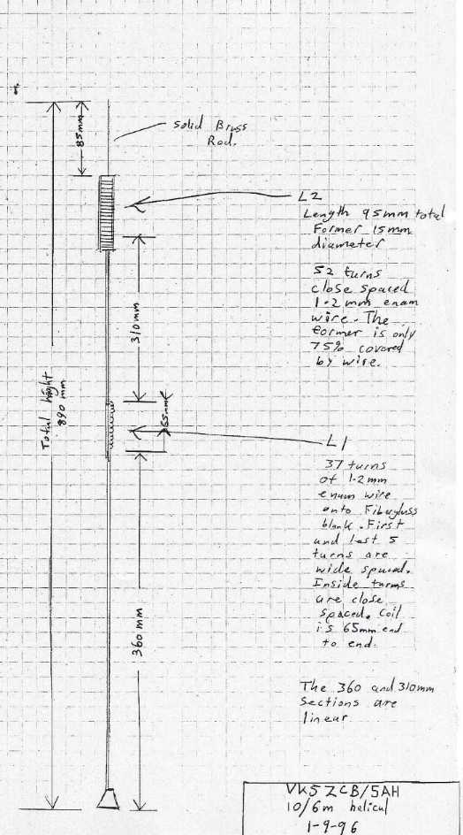
This antenna has been constructed using either a old CB whip or a 2m 5/8 whip stripped down. I have been using it on my 4WD for years and had many good contacts. If you strip down an antenna and heat srink it again then be aware that some heatshrink tubes have a habbit of shifting the antenna resonance particularly when there are helical windings involved. The former for L2 could be a peice of 20mm conduit with a few adjustments. Build the antenna roughly to size and adjust the 6m section first below L2 . Then move on to the 10m adjustment above L2 after.
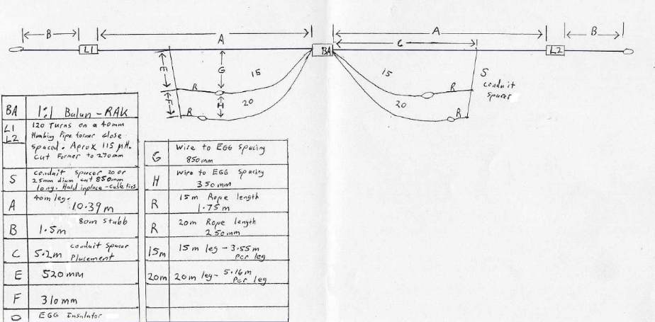
Construction Tips:- None of the dimensions could be said to be critical except perhaps the 80m Tips (B) and the G/H spacings. Build the Antenna complete before adjusting or trimming anything. The Antenna was erected at about 25 feet in reasonably free space in a horizontal plane. Dimensions would differ in a sloping configuration and extra ropes may be needed from the bottom of the spacer conduits to the ends of the inductors perhaps. Feed the antenna with a 1:1 balun and be careful the common feed points dont get twisted up near the balun. The coils are not critical. Half a dozen turns here or there wouldnt be critical but would tend to affect the 80m tips a little. The resonant frequency will tend to drop typically 20-30 Khz on both 80 and 40m when the coils are soaked in rain. They could be sealed perhaps with polyresin but be careful they dont become too heavy. The spacer conduits were drilled through and threaded onto the A section and held in place using cable ties to stop it from sliding along the wire. The coils were wound with fine stranded insulated wire of about 2mm total thickness (insulation included) . The important thing is to be able to get that many turns onto the former close spaced.
Adjustment:- Start by adjusting the 40m sections (A) and then the 80m tips (B) then adjust the 20m section followed by 15m lastly. Be careful to make all adjustments so as to keep the antenna symetrical particularly the 80m tips. As a guide the 80m tips will adjust at about 40Khz per inch and the A section will adjust 40m by about 10Khz per inch. The 20 and 15m legs have little effect on 80 or 40 but the 20m legs will effect the 15m section. Do not be tempted to bring the 15m sections up closer to the 40m section as strange things start to happen on 15m. Dont be decieved adjusting the 15m legs. The SWR will appear to drop nicely at about 20.8 Mhz but this is in fact the 40m section coming into play. If problems are encountered making it work on 15m then disconnect the upper section of the antenna (A) from the balun but leave it physically in place. Then adjust the 15m section and finally reconnect the upper section. The SWR will rise slighly on reconnection and the best you will get is about 1.6:1 SWR . My solid state radios seem quite able to still deliver 100 % power forward into this sort of load.
Performance and Characteristics:- The antenna performs as a standard dipole on all bands except 15 and 10m. It has a bit of end fire on 15 and 10m making the antenna work almost omnidirectional. Particularly so on 15m due to the 1.5 wavelength section from 40m The Bandwidths of the 2:1 SWR points is as follows on each band.
80m - 40 Khz, 40m - 250 Khz, 20m - 500 Khz, 15m - 21.0-21.350
Other Bands:- I have not tried the WARC bands but the antenna seems to work reasonably well on 10m using a tuner. The SWR without is about 5:1 .
160M- Try adding about 6.9m to the 80m ends and it works on 160 . I used some aligator clips near the 80m end Egg insulators to clip/unclip the 160m sections as i can get my antenna ends up and down fairly quickly on pulleys. The antenna adjusts on 160m at about 3Khz Per Inch.
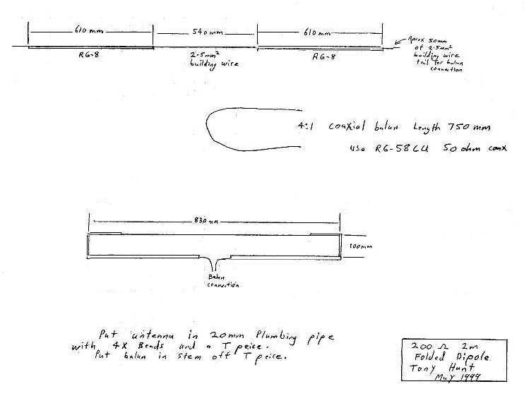
This folded dipole has a 200 ohm feedpoint providing a good match for 50ohm coax through the 4:1 coaxial balun shown. The feed impeadance is achieved by making one side out of a thinner conductor (2.5mm square building wire) .The SWR is very low across the band. This antenna has been in use on the Adelaide 10m repeater, 2m gateway.
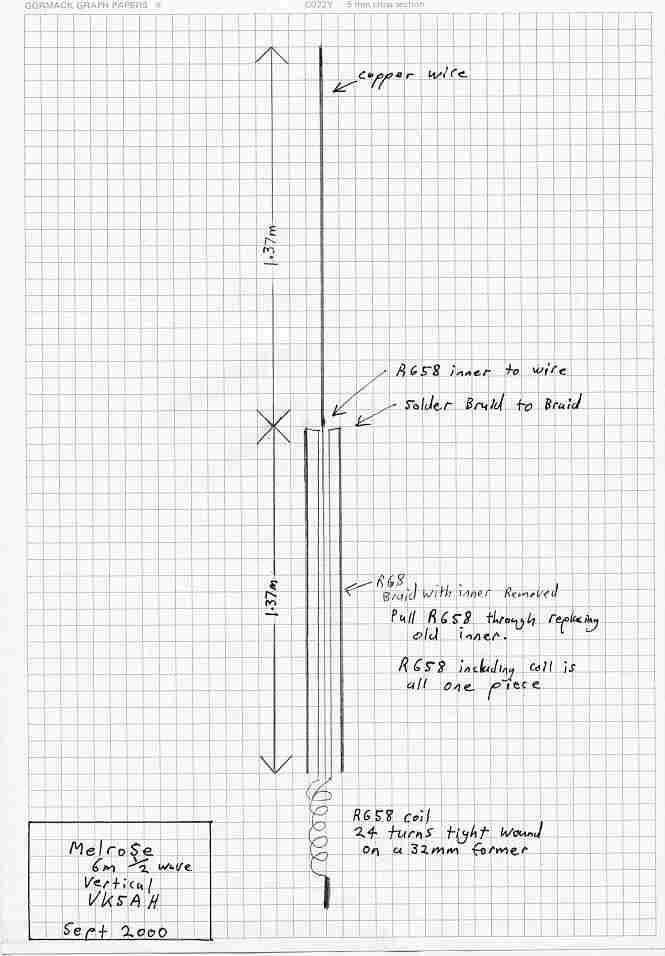
This half wave vertical is made from coax. Both RG8 and RG58 is used. Pull out the inner conductor of a length of RG8 and whilst doing this pull through a length of RG58 in its place. The coil can be adjusted to shift the centre frequency of the antenna. Just take turns off to shift the frequency up or add turns to shift it down. I have put my own antenna into a length of 40mm plumbing pipe. I made this antenna up whilst on holidays in a place called Melrose so its called a "Melrose" .
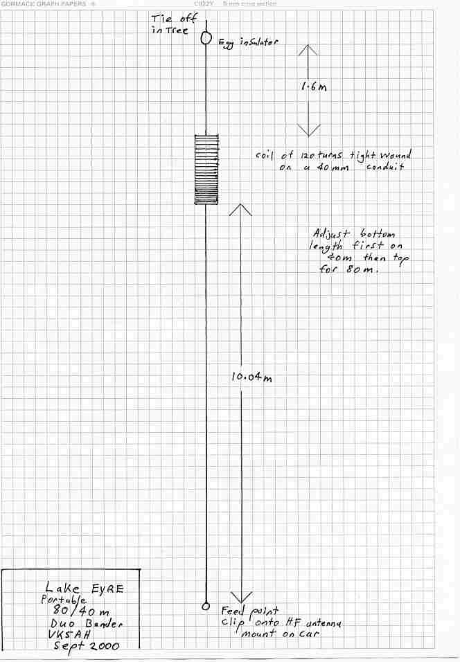
I made this antenna up while camping near Lake Eyre. It was a great improvement on the mobile whip. It just clips onto the mobile mount instead of the whip, the other end is hoisted up into a nearby tree or support. I have generally used the antenna at a 45 degree angle as a sloper. The coil is essentially a RF choke like the 4 Bander dipole design. Try adding about 6.9m to the 80m ends and it works on 160 . The antenna adjusts on 160m at about 3Khz Per Inch.