802.11b Radio network training manual
June 24th 2002 Ver 1.1
1. Introduction
The VoIP pilot project uses a computer network to carry
telephone calls between Thimphu and customers in Limukha and Gelephu. The
network uses the same TCP/IP protocols that are used on the Internet and common
computer LANs. In addition the actual telephone calls are placed and
connected using another group of protocols known collectively as
H.323.
Often computer networks are built using 10BaseT or unshielded
twisted pair cables but in this case we are using digital radios to send and
receive the data. This is a less expensive way to cover long distances
especially over rough terrain. However the downside is that generally the
connections aren't as fast as wired or fiber media, and latency is more
variable.
There are to parts to our network, the backbone and the last
mile delivery. The backbone of our network is conceptually very similar to the
telephone microwave network. They are both built using high bandwidth point to
point links. Additionally point to point links can be full duplex which gives
you twice the bandwidth of a simplex link, however for this pilot project our
802.11b backbone is simplex. Compare that to the last mile delivery which is
point to multi point and can generally use lower speed connections, and is
simplex by necessity. This is similar to what is known as Wireless local loop or
WLL in a typical telephone installation. In Bhutan the VHF telephones are an
example of WLL.
Last but not least the system is easily capable of
providing Internet access. The only missing piece is a billing system for
it.
2. Assembly
For the pilot project we used Cisco BR342 bridges for are
main repeaters. These were used in point to point configurations for the
backbone, and point to multi point for the last mile delivery to the customer
premises equipment (CPE).
Notice that for the pilot project the backbone
was the same speed as the last mile. In the future we would use higher speed
equipment for the backbone.
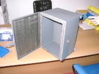
The repeater boxes are simple weather tight
boxes that hold most of the components of a repeater. The major components of a
repeater are:
- A radio (BR342)
- pig tail (between radio and DC injector)
- DC injector (To power the amplifier)
- A bulkhead connector (which takes the signal path through the box)
- Coax feeder cable
- Bidirectional Amplifier (pulls in weaker signals and extends the range of
the repeater)
- Antenna (depending on application could be a dish, Yagi, or omni)
The other supporting components are:
- Weather tight box
- Small shelf to mount equipment on
- DC-DC converter (for stable power to the repeater)
- Timer (As backup way to power cycle the repeater once a day in case it
crashes)
- Misc mounting hardware for the box and antenna
|
|
|

|
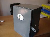
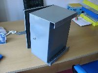
Weather tight Box
|
Front
|
Back
|
Hand painted
logo
|
The only minor problem with the boxes
is that the angle iron mounts on the back should have protruded away from the
top and bottom surfaces.
To assemble the components, make sure that the
proper holes are pre-drilled and line up correctly. Also check that the shelf
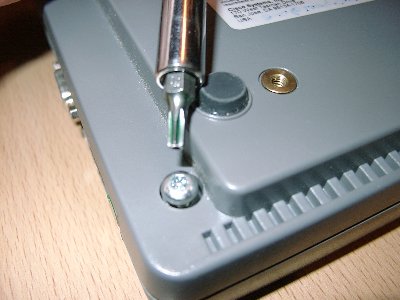
fits inside the box. Take apart the radio using the special Torq bit
required. and pull out the pigtail. Be sure to note which connector on the
wireless card that it was plugged into. Then put in the new pigtail with the
male N connector. Route it through the hole nearest the end of the wireless card
so that more of it will reach outside of the radio. Then mount the timer, DC-DC
converter, and radio as shown.
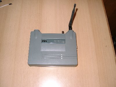
|
|
A brand new Cisco BR342 with
antenna
|
Take out the four screws with the special
screw driver
|
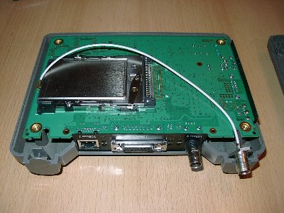
|
|
Original pigtail with R-TNC
connector
|
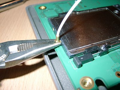
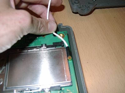
Carefully pull out the MMCX connector with
small pliers
|
|
|
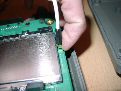
Carefully snap in the connector for the new
pigtail
|
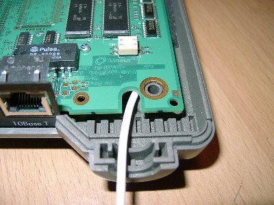
Prepare to route the new pigtail out the
closest hole
|
|
|
It's easier to flip the board over so the
pigtail is on the bottom
|
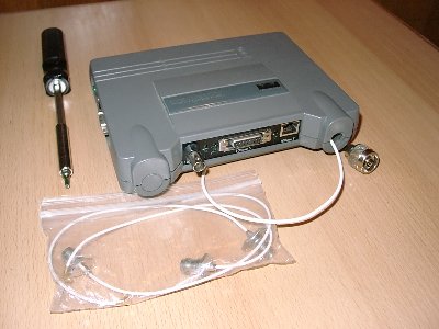
All done! Save the original pigtail in a
safe place
|
|
|
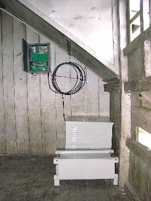
An example repeater
installation
|
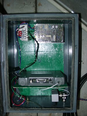
Parts layout in a repeater
box
|
3. Installation
3.1 Site survey
To install a repeater first do a quick site survey.
Primarily you want line of sight to all clients and other repeaters. This
usually means locating the repeater on a hill top somewhere. Also it is helpful
to take a GPS reading at all sites so you know how far apart the antennas are.
Our very conservative rule of thumb is that one shouldn't try to place two 8dbi
omnis more than 8km apart, though two dishes could be 20 or 30km apart. Also
when doing a site survey keep in mind that you don't want any obstacles near the
path like roof tops, corners of buildings etc. To repeat, just line of sight is
just not good enough. As mentioned above the repeaters have amps. These are
bi-directional which means they amplify the receive signal as well as the
transmitted one. The CPEs don't have amps but do have higher gain Yagi antennas.
This seems like good cost effective way to build a reliable system. However if
you end up with one customer site way out by themselves you might consider
installing an amp at their site and connecting to an existing repeater instead
of putting up another repeater just for them.
Basic repeater installation
usually is done on a telephone pole or preexisting tower. It might be possible
to also mount one on a GI pipe.
3.2 Lightning protection
Most of the time the antenna will be mounted up
high in an open area. To protect it against lightning strikes a lightning rod
must be mounted one or two meters higher on the same pole, and a heavy gauge
bare coper wire should run down to your earthing on the opposite side of the
pole from your coax feeder cable. The preexisting microwave towers have a strong
two meter pipe at the very top that the lightning rod is mounted on, It's
probably a bad idea to mount an antenna on this pipe even though it seems very
convenient.
Typically the antenna and lightning rod are U-bolted to
angle iron that is U-bolted to the top of the telephone pole or tower. Often the
U-bolted are made out of all thread.
The weather tight box is also
mounted to the pole at a convenient hight using all-thread.
Wrap all
exposed connections with waterproof tape and then wrap again with with standard
or UV resistant electrical tape.
Earthing. there seem to be two ideas for
earthing. use one ground point or two. If you use one then the equipment ground
wire from the box should be attached to the lightning ground wire as it enters
the ground. If you use two separate grounds which is more difficult then
the lightning ground must be better than and a more direct path to ground than
the equipment ground. the equipment ground must also be many meters away from
the lightning ground so that the voltage surge caused by a lightning strike in
the surrounding ground is not transfered into the equipment.
It's very
easy to have just one ground in a solar powered site. For commercial powered
sites you must either add to the existing ground or be very careful to make the
lightning ground much better than the commercial ground, otherwise you are just
begging the lightning to run through your equipment and burn it up.
For
more information on erecting telephone poles and digging earthing pits consult
your local experts.
4. Configuration
Radio Configuration
The Cisco BR342s used in our
pilot project are initially configured over a serial port. Later after they are
on the network the configuration can be changed by using a web page interface or
by telneting to them. To connect to the serial port set your terminal emulation
program to 9600 baud 8 data bits no parity and one stop bit (9600
8N1).
There are only a relatively few settings that need to be changed to
bring up a repeater. Here are the most important, for a complete list see the
Cisco documentation. The serial interface is organized into a set of nested
menus. You navigate through them by typing the number of the item you want and
then typing in the new value for that option. Sometimes you need to put quotes
around text that has multiple words. For a band new radio the first menu you
will see is this:
Option Value Description
1 - Configuration   [ menu  ]   - General configuration
2 - Statistics      [ menu  ]   - Display statistics
3 - Association     [ menu  ]   - Association table maintenance
4 - Filter          [ menu  ]   - Control packet filtering
5 - Diagnostics     [ menu  ]   - Maintenance and testing commands
6 - Logs            [ menu  ]   - Alarm and log control
7 - Privilege       [ write ]   - Set console privilege level
8 - Close                       - Close the telnet session
9 - Help                        - Introduction
Enter an option number or name
>
For one
that has already been configured you will probably get the privileged menu which
looks like this:
Option Value Description
1 - Privilege   [ off ]   - Set console privilege level
2 - Close                 - Close the telnet session
3 - Help                  - Introduction
Enter an option number or name
>
So select "1", then "w"
for write access, and type in the password. This will take you to the main menu.
Then you will want to press "1" for the configuration menu. From there we set up
the radio.
4.1 Identity
The first thing to set is the radio's identity. The most
important items in this menu are:
2 -
Name
4 - Inaddr
5
- Inmask
6 -
Gateway
If you like you can optionally set the DNS servers but it is not
necessary. Here is an example of a repeater with these values set:
     Option              Value            Description

1  - Bootp_DHCP   [       off       ]   - Use BOOTP/DHCP on startup
2  - Name         [  "Multithang"   ]   - System name
3  - Class        [    "BR500E"     ]   - DHCP class id
4  - Inaddr       [ 202.144.156.241 ]   - Internet address
5  - Inmask       [ 255.255.255.000 ]   - Internet subnet mask
6  - Gateway      [ 202.144.156.254 ]   - Internet default gateway
7  - Routing      [      menu       ]   - IP routing table configuration
8  - Dns1         [ 202.144.128.200 ]   - DNS server 1
9  - Dns2         [ 202.144.128.210 ]   - DNS server 2
01 - Domain       [      ".bt"      ]   - Domain name
02 - Location     [       ""        ]   - System location
03 - Contact      [       ""        ]   - System contact name

Enter an option number or name, "=" main menu, <ESC> previous menu
>
For
example if you want to change the IP address you would press "4" then type in
the new address like 10.2.0.33.
4.2 Ethernet
The ether net menu is pretty easy. If it is a standalone
repeater then you can just turn it off using the first option. Otherwise set it
for 10BaseT instead of auto, and you;re down with this menu. Option Value Description
1 - Active [ on ] - Connection active
2 - Size [ 1518 ] - Maximum frame size
3 - Port [ 10baseT ] - Port selection
4 - Staletime [ 350 ] - Wired LAN node stale out time
Enter an option number or name, "=" main menu, <ESC> previous menu
>
4.3 Console
Mainly you set the read and write passwords from the console
menu. The read password lets someone see the radio's configuration but not
change anything, the write password lets one do anything.
     Option          Value      Description

1  - Rpassword                - Set readonly privilege password
2  - Wpassword                - Set write privilege password
3  - Remote        [  on  ]   - Allow remote operators
4  - Telnet        [  on  ]   - Allow telnet connections
5  - Http          [  on  ]   - Allow http connections
6  - Display                  - Display the remote operator list
7  - Add                      - Add an operator host
8  - Delete                   - Remove an operator host
9  - Communities   [ menu ]   - SNMP community properties
01 - Type          [ ansi ]   - Terminal type
02 - Port          [ menu ]   - Serial port set-up
03 - Linemode      [ off  ]   - Console expects complete lines

Enter an option number or name, "=" main menu, <ESC> previous menu
>
So
press "1" to change the read password or "2" to change the write password, and
it will ask you to type the new one twice to make sure you don't make a
mistake.
4.4 Radio
Last but not least is the radio configuration. The two most
important parameters are the SSID and Root mode. The SSID is like the name of
the network that the radios are a part of. There can be other networks with
different SSIDs and the radios of one won't talk directly to the others. They
will still route packets to any IP address through the 10BaseT interface but
they won't talk over the radio link to anyone who has a different SSID from
theirs. The Root mode controls weather the radio is a master or a slave. If it
is on then that radio is considered the path back to the rest of the network.
Non root radios must find a root radio to be their parent and they will send any
packets that are not for their clients back to their parent to deal with. Root
radios almost always have a 10BaseT connection to the rest of the network. Non
root radios almost never do, (or at least the way they are used in our
network).
     Option           Value        Description

1  - Ssid          [ "BTnet" ]   - Service set identification
2  - Root          [   on    ]   - Enable root mode
3  - Rates         [  1_11   ]   - Allowed bit rates in megabits/second
4  - Basic_rates   [    1    ]   - Basic bit rates in megabits/second
5  - Frequency     [ "auto"  ]   - Center frequency in MHz
6  - Distance      [    0    ]   - Maximum separation in kilometers
7  - World         [   off   ]   - Enable world mode
8  - I80211        [  menu   ]   - 802.11 parameters
9  - Linktests     [  menu   ]   - Test the radio link
01 - Extended      [  menu   ]   - Extended parameters

Enter an option number or name, "=" main menu, <ESC> previous menu
>
Here
is where you set the SSID and Root mode. The next thing you may want to set is
the Frequency. Usually it's not a good idea to leave it as "auto". There are
eleven possibilities, and if you are on a tower with a DRMASS system then you
probably don't want to use the lowest one which overlaps a bit with the DRMASS
frequency. If you want to get an idea what frequencies are in use the carrier
activity monitor under Linktests. (See testing below).
Out of the eleven
or so choices there are only three non-overlapping channels that you can use
because each channel is about 25MHz wide [3]. This
usually means that if you want to use all three channels in the same area then
you set your three root repeaters to 2412, 2437, and 2462. But you should use
2417 instead of 2412 if you are on a tower with DRMASS.
Under the I80211
menu you will see the Encapsulation submenu. It's best to change the
encapsulation to RFC1042.
Option Value Description
1 - Encap    [ RFC1042 ]   - Default encapsulation method
2 - Show                   - Show encapsulation table
3 - Add                    - Add a protocol encapsulation method
4 - Remove                 - Remove a protocol encapsulation method

Enter an option number or name, "=" main menu, <ESC> previous menu
>
Under
the extended menu you will find Bridge_mode and Power. Set the bridge mode to
access_point. For a 50 foot coax feeder a good power setting is 50mw so you
should set it to 50. The amp which is right next to the antenna will boost it up
to about one watt. If you set the power too high then the amp will distort the
signal and you will get more errors. If you set it too low then the amp will not
be able to boost it all the way to one watt. A good rule of thumb is to start in
the middle and work down till a multicast test starts to show more errors, then
go up one notch. This should give you adequate rain margin and cause less
interference to neighboring antennas. It seems counter intuitive but just
turning up the power when your having problems can often make things worse
instead of better.
Option Value Description
1  - Bridge_mode   [ access_point ]   - Bridging mode
2  - Time_retry    [      8       ]   - Number of seconds to retry transmit
3  - Count_retry   [      0       ]   - Maximum number transmit retries
4  - Roaming       [   directed   ]   - Type of roaming control packets
5  - Balance       [     off      ]   - Load balancing
6  - Diversity     [     off      ]   - Enable the diversity antennas
7  - Modulation    [     cck      ]
8  - Power         [      50      ]   - Transmit power level
9  - Fragment      [     2048     ]   - Maximum fragment size
01 - Options                          - Enable radio options

Enter an option number or name, "=" main menu, <ESC> previous menu
>
The web interface has similar menus and it is much easier to find and
change things. Sometimes too easy! Just one wrong tap of the mouse button can
make the radio unaccessible and require you to make a trip out to the site to
correct the problem over a serial cable. So please be careful... And that is
about it for the radio configuration. For the other parameters you could visit
the Cisco site or view the documentation on the CD ROM that comes with the
radios.
5. Testing
From the diagnostics menu you can do some testing and trouble
shooting. When you install a new repeater you'll probably want to check the
error rate to it's parent.
Option Value Description
1 - Network     [ menu ]   - Network connection commands
2 - Linktests   [ menu ]   - Test the radio link
3 - Restart                - Restart the unit
4 - Defaults               - Return to default configuration
5 - Reset                  - Default parts of the configuration
6 - Load        [ menu ]   - Load new version of firmware

Enter an option number or name, "=" main menu, <ESC> previous menu
>
Under
the diagnostics menu you will find Linktests. Here there are several useful
tests. Signal strength provides a quick indication of the relative signal
strength and quality of another device. The multicast test is probably the most
useful for testing a radio link between a client and it's parent. The unicast
test is the same as a standard ping so you could use that to any destination to
get an idea of average losses and round trip times.
     Option          Value      Description

1  - Strength                 - Run a signal strength test
2  - Activity                 - Activity by frequency
3  - Multicast                - Run a multicast echo test
4  - Unicast                  - Run a unicast echo test
5  - Remote                   - Run a remote echo test
6  - Destination   [ any  ]   - Target address
7  - Size          [ 512  ]   - Packet size
8  - Count         [ 100  ]   - Number of packets to send
9  - Rate          [ auto ]   - Data rate
01 - Errors                   - Radio error statistics
02 - Autotest      [ once ]   - Auto echo test
03 - Continuous    [  0   ]   - Repeat echo test once started

Enter an option number or name, "=" main menu, <ESC> previous menu
>
The
network menu is useful for doing simple ping tests or to telnet to another
radio. especially if the radio has no IP address or for some other reason it's
not usable. If you can connect to some radio on the network over the serial
cable, or telnet to it then you can use the connect option in the network menu
to telnet to another radio by just giving it's MAC address. Cisco calls this the
network address. This is a very handy feature for fixing misconfigured
radios.
    Option        Value        Description

1 - Connect                  - Start telnet session
2 - Escape    [ "^X^Y^Z" ]   - Connection escape sequence
3 - Ping                     - Send an IP PING packet
4 - Find      [   off    ]   - Flash LEDs to find unit

Enter an option number or name, "=" main menu, <ESC> previous menu
>
6. Operation
For general monitoring of operation the Statistics menu is
useful. Select "5" to show the network map, Then "A" for all. This will give you
a display of all the nodes on the network. The web version of this will
continually update the display.
     Option          Value     Description

1  - Throughput              - Throughput statistics
2  - Radio                   - Radio error statistics
3  - Ethernet                - Ethernet error statistics
4  - Status                  - Display general status
5  - Map                     - Show network map
6  - Watch                   - Record history of a statistic
7  - History                 - Display statistic history
8  - Nodes                   - Node statistics
9  - ARP                     - ARP table
01 - Display_time   [ 0  ]   - Time to re-display screens
02 - IpAdr          [ on ]   - Determine client IP addresses

Enter an option number or name, "=" main menu, <ESC> previous menu
>
There
is a handy software package called Cricket that will monitor and graph the
traffic and errors for each radio. Find out from your system administrator what
the URL is for this page. In particular a lot of RF errors for any radio would
suggest it has a LOS or power problem. A lot of hold off errors mean that there
is interference from another source, like DRMASS. Usually you try a different
frequency that seems to be unused and that fixes the problem.
7. References
[1] Introduction to Networking: http://www.thelinuxreview.com/howto/intro_to_networking/book1.htm
[2] Linux Headquarters: Network Configuration Using the Command
Line: http://www.linuxheadquarters.com/howto/networking/networkconfig.shtml
[3] Tutorial on 802.11b spectrum usage http://www.euro.dell.com/countries/eu/enu/gen/topics/vectors_2001-wireless_deployment.htm