An ultra portable QRP CW-transceiver for 20 meter.
MY FIRST QRP RIG "THE BAREFOOTER"
An ultra portable QRP CW-transceiver for 20
meter.
Simple!
Indeed the rig is really simple! When I found the design, I
did not believe that it was possible to make QSO's with it as its simplicity is
such a contrast with the standard amateur transceiver with high power, superhet
receiver and other complex circuits.
But it should be a very nice experiment
to take such a simple transceiver with me on Holidays to Norway and Sweden!
Holidays
Within two weeks this 20m QRP rig was ready to take with
me on holidays to Norway and Sweden. And results were astonishing! Almost every
day it was possible to make a QSO with a radio amateur living nearby my home
QTH. With ease, also a lot of other QSO's were made. The antenna was a dipole
between trees when camping in the woods. Little stones or branches are used to
throw the ropes in the trees. Or the same dipole is also used as inverted Vee
with the center at 4 meters using a fishing rod. Also a quarter wave vertical,
using the same fishing rod, 6x2meters radial wires as groundplane was
used.
All antenna's worked well, I never had an SWR meter with me. The
vertical with the radials was made from loudspeaker wire and a PL259 plug, sold
in a local shop in Sweden. The wire length was calculated and I never verified
the SWR...
As this simple rig worked much better than expected, I also made a
two band version for 40 and 20m.
MY FIRST QRP RIG
The design is based on an article in the book Solid State Design for the Radio Amateur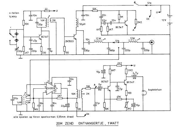
Circuit diagram, sorry for the Dutch language.
LF amplifier
The coupling between the two transistor LF amplifier
and the mixer is via a LF transformer. And that is a problem if you use the rig
nearby power lines or transformers, a loud 50 Hz hum is heard. I took a LF
driver transformer of a balanced final LF amplifier from an old transistor
radio.
The two transistor LF amplifier drives the earphones. Connect both
earpieces in series instead of in parallel for much more audio output.
During
transmission, the side tone generator is coupled via the 2M2 resistor (select it
for the side tone level you want to have) to the LF amplifier. Although there is
not so much selectivity, the receiver sounds good and I always listened to it
with pleasure. The 2k2 potentiometer is for the battery-empty indication.
Connect the rig with the minimum supply voltage. While transmitting, adjust the
potentiometer so that the side tone dissapears.
VXO
The VXO frequency is varied by a simple variable mica
capacitor. Via the 5 pFcapacitor, the VXO signal is fed to the mixer.
I used
two crystals: 14045 and 14060 kHz, but of course you can use any frequency you
like.
For the two band version, the 120 pF capacitor is removed and the
tuneable coil is replaced by a FT37-43 ferrite core (same windings) and I use
only one crystal per band.
Transmitter part
The VXO signal is amplified to 1 watt by a
transistor 2N3553. The output is filtered in two pi sections. Why is switch S1b
in the middle of the filter instead of at the end? I really do not know. In the
two band version I used two 5 pole filters and switch S1b at the end of the
filters. Solder a 100 pF capacitor between the collector and emitter of the
2N3553 for stability reasons.

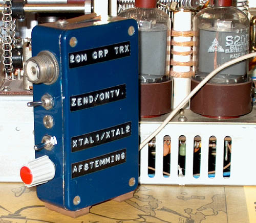
The inside view, all "Simple QRP" technology.
Performance
I have had a lot of fun with this rig and used it
during holidays under all kinds of conditions. It always worked fine!
The
receiver is sensitive enough, some AM detection of strong broadcast stations is
possible, the audio transformer gave problems when camping close to overhead
power lines, there is no volume control, but it was real fun to use this rig.
The antenna was a dipole between trees or as inverted Vee, the middle at 4
meters using a 5m fishing rod as a support. I also used a vertical (vertical
wire mounted to the vertical fishing rod and 6 radials of 2 m length).
The
rig is also used in the shack with a long wire antenna and a tuning unit. A lot
of perfect QSO's are made, even long chats.
I also designed a new version,
the 4 band HappyHoliday trx, also somewhere on this site.
RX current: 30 mA (quite high)
Transmit power: 0.6 W at 9 V; 1.5 W at 12
V
Harmonic suppression: Yes!
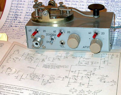
The two band version of the Barefooter and the
original
article in the book Solid State Design for the Radio Amateur.