Introduction
From the email I have received many builders want simpler stuff to experiment with and that theme spawned this project. I have many transistor radio construction books from the late 1960s and 1970s and it was very common to see a single transistor used as a product detector in both DC and Superhet receivers. A single-ended transistor for a product detector has become unpopular for good reason. They are prone to unwanted AM radio detection by strong in-band and out-of-band shortwave and commercial broadcast radio stations and have poor IMD characteristics. Bandpass filters may reduce out-of-band interference but depending where you live may not be enough to reduce the level of demodulated in-band signals. Nevertheless, if the application is for a low-cost, lower performance purpose, single-ended transistor detectors can be fun to experiment with and offer substantial conversion gain.
This tranceiver project requires no tuning and apart from the LM386, is built exclusively from low-cost BJTs, the 2N3904 or 2N3906 which are my ultimate popcorn parts. Please beware, this project is not an exercise in good RF or audio design and the whole goal was to build a novelty-grade tranceiver that would be fun and easy to replicate. I have received email from many amateurs who have offered criticism of the QRPHB site and while the comments are greatly appreciated, this site's purpose was never for learning the latest and best radio electronic design techniques. There are many excellent sites for that and some are listed in the links section on my info page.
This transceiver was built for the 40 meter band and this band probably represents the worst-case scenario for a single-ended product detector. The number of shortwave broadcast stations in and around this amateur band is staggering. Why did I do it? I had the crystal and wanted to see how bad the worst case scenario would be. I gained an immense amount of knowledge building this project and had fun too. I hope that this project will spawn some experimentation by some of the builders who seem to frequent this web site. This project turned out better than I expected it would and is both enjoyable to build and operate.
Local Oscillator
I wanted to make the local oscillator quite fool proof which meant using a "no-tune" Colpitts. I also wanted no transformers and so the buffer shown was used. Q2 provides some voltage gain and emitter follower Q3 reduces the output impedance to drive the product detector and transmitter chain.The Q1 68 pF feedback capacitor is not critical and a 56 pF worked just as well in my experimentation.
When Q4 is switched on during transmit mode, it drops the oscillator frequency by 638 Hertz. This is needed so you will not be zero-beat with another station and hear nothing in the cans. I experimented with the total capacitance of the offset capacitors which in the final design totals 78 pF (C1 plus C2). With a single 100 pF capacitor, the offset frequency was 482 Hertz. With a 82 pF plus a 10 pF ( total 92 pF ) the frequency offset was 553 Hertz. With a single 68 pF capacitor, the frequency offset was 748 hertz. I finally settled on the 78 pF total capacitance as shown in Figure 1, although the single 68 pF capacitor would probably be just as good a choice. I used NP0 ceramic capacitors for the 2 offset capacitors because of their good frequency stability and also because I have many on hand in my junk box. You can use other capacitor types as well if you do not have the NP0 ceramic units, but remember to test the final product for short-term frequency stability.
I layed the crystal on its side and soldered right onto the crystal leads. Keep component lead lengths reasonably short for best results.

Product Detector, Audio Power Amp, Sidetone and Mute Circuits
Product
Detector:
I tried four different single-ended BJT product
detectors while building this project and settled on the one shown as it had the
most conversion gain and sounded the best to my ears. If you know of a better
one, please send me an email. One thing I learned is that single-ended BJT
detectors are very prone to effects of power supply hum. To better decouple the
detector, the Q6 active decoupler was used. Any 60 cycle hum that gets into Q2
will be greatly amplified by Q7 and then the LM386. If you use this project as a
battery-only tranceiver a simple decoupler consisting of a 1K resistor with a 10
- 22 uF electrolytic capacitor may be substituted for the Q1 circuit.
Note
the 10 uF and 0.1 uF capacitors on the emitter of Q7. This is to bypass both
audio and RF energy. There is some RF in the output of this detector due to its
lack of balance.
A simple low pass filter consisting of a 10K resistor
and two 0.022 uF capacitors is used to launder some of the high-pitched CW din
coming out of the detector. The cut-off frequency was designed for 723 Hertz.
This blocks any RF coming out of the detector and also seems to help reduce the
interference from short wave radio stations.
Note the tuned input of the
detector. This simple bandpass filter helps to eliminate out-of-band RF energy
from being demodulated. When I first built and tested the receiver, I connected
my 40 meter dipole to the RF input of the product detector and a loud AM band
country radio station was heard in the phones. I then added the simple bandpass
filter, reconnected the antenna and the country station was gone.
During the
nighttime, I could hear shortwave QRM but no local broadcast stations at all.
Consider the bandpass filter compose of T1 and the 68 pF capacitor:
L1 = 7.4
uH, which is an XL of 333 ohms at 7.040 MHz. To resonate the filter, a single 68
pF capacitor is used. I elected not to use a variable peaking capacitor for
simplicity and frugalness. I learned this technique from W7ZOI. You can add a
variable tuning capacitor for peaking the tuned circuit if you like, but it
works fine without it. For this whole project, all the RF capacitors used were
cheap monolithic ceramic capacitors from Digi-Key (COG) . They have thick leads
and are perfect for Ugly Constructing. The T1 secondary winding consists of 39
turns of # 26 wire on a T50-2 torroid core, I tried tapping the secondary in a
couple of places to provide a better impedance match to Q2. In the end, I found
that connecting the high impedance end right to Q2 via a 470 pF capacitor as
shown in Figure 2 gave the best results and also was the simplest approach. The
T2 primary is 4 turns of # 26 wire wound in the same direction over the grounded
end of the secondary winding. The primary winding connects to the antenna via
the transmitter series resonant filter and output filter.
Q2 is quite busy
with lots of capacitors. Keep your leads as short as possible for best results.
The final audio stage is the LM386 audio chip operating in the high-gain
mode by virtue of the capacitor connecting pin 8 to pin 1. I originally kept the
LM386 in the low-gain mode and added another preamplifier stage which was a
2N3904 biased to correctly terminate the low-pass filter. While it gave somewhat
cleaner audio and more volume, it also added more broadcast radio into the LM386
and increased the project parts count. Thus, I dropped this stage and went with
the high gain LM386 used by many authors in simple receiver projects such as
this one. I did try another audio PA using a complimentary pair consisting of
one 2N3904 and one 2N3906, but it added too much to the parts count and was
abandoned.
Sidetone Circuit:
The sidetone
is W7ZOI's popcorn multivibrator that I first saw him use in Solid State Design
for the Radio Amateur published by the ARRL. I used 120K base resistors to lower
the frequency somewhat from the original 100K base resistor design. The 1K
resistor from the multivibrator to ground is also from W7ZOI and lowers the
output voltage of the circuit as it is extremely loud when boosted by the LM386
set in the high gain mode. The 10 Megabyte resistor is also used to lower the
volume of the side tone during keying. Change this value up or down to suit your
taste. The multivibrator gives a harsh square wave tone, but is cheap, easy to
build and always starts.
Mute Switch:
It
may surprise some that I used a mechanical switch to mute the receiver during
transmit mode. I tried a simple transistor switch that grounded the product
detector output during transmit and indeed it worked fine. The problem was a
very loud popping sound caused by the PNP switching transistors in the circuit.
The sound was amplifyed by the product detector and then by the LM386 which is
in the high gain mode. This popping was deafening. If the mute was applied
before the Q11 transistor was keyed, the popping was tolerable. I tryed many
circuits and ideas, but was unhappy with the results. Some of the latest QRP
receiver designs use MOSFETS for muting and this was not an option for this
project as I wanted to stick with cheap BJTs. When building, by placing S1 right
next to the 10K volume pot you can use a very short wire to ground the input of
the 10K pot when the switch is closed. The short length of wire will minimize
the potential of adding hum and noise to the product detector output. Keep your
sidetone to potentiometer connecting wire as short as possible too.
Transmitter
The PA is two 2N3904s (Q13 and Q14 ) in
parallel. I learned this technique from the late W1FB. Emitter degeneration is
used to prevent one BJT from hogging current over another if they have different
gain and also provides some thermal stability. I used 4.7 ohm resistors because
they were in my junk box. Using any low value from 4.7 to under 10 ohms should
work okay. The power output for this transmitter will vary from factors such as
your actual transistor gain, VCC and your transformer, but should be around
one-half watt. You can parallel 3 or 4 transistors if you like, but heat sinks
will probably be required. I have done this in the past and glued pieces of PC
board onto the 2N3904s for heat sinks. I did not use heat sinks on this project
and so far no problems have occurred.
If you have T37-2 torroid cores,
they would be even more suitable for L1 and L2. The 0.97 uH would require 16
turns of #26 AWG on a T37-2 core. L3 is a bit of a pain with 46 turns of #28 AWG
on a T50-2 powdered iron core. For the RF choke RFC1, I wound 6 turns of #24 AWG
on a ferrite core, a FT37-43. Use whatever you have on hand, as long as it is
rated to handle the currrent of your chosen PA stage. The transformer T2 is
wound by winding the primary 12 turns over the ferrite core leaving a space or
gap between the ends of this winding of about 1/8th of an inch. The secondary 3
turns are wound with even spacing over the primary windings so that the primary
and secondary start and finish wire ends are close together. It is not critical
however.
I did not have a zener diode to put on the transmitter PA to
protect from SWR damage during inadvertant no-load transmission. It would be a
good idea to add one. A 33 volt 400 mw zener could be added right to the
collector of Q14 with the anode to ground.
Transmit-Receive Circuits
The antenna is connected
to both the receiver input and the transmitter output at all times. While
transmitting, the back-to-back diodes in the circuit conduct and prevent the RF
level from exceeding 0.7 volts RMS. The beauty of this system is that the low
pass filters and the series resonant bandpass filter provide additional input
filtering for the receiver. The transmitter filters combined with the simple
bandpass filter connected to the product detector really help reduce the
presence of unwanted RF signals present in the detector. I heard no local
broadcast radio whatsoever, however shortwave radio is often present,
particularly later on at night but generally not at any great amplitude much to
my surprise. This will vary with location and I imagine in Europe could be much
more of a problem.Construction Ideas
I suggest start by
drawing the local oscillator. The output of Q3 should be accessible by both the
product detector and transmitter stages. The transmitter output low-pass filter
and series resonant receiver feeding circuit should be layed out away from
transmitter stages Q12to Q14. In addition the product detector, low-pass filter
and audio output stages should be layed out in a linear fashion with short
leads. You may have to draw your layout several times before you are satisfyed
with it.
You may have your own building techniques in mind and the
following is only suggested. When actually building, start with the LM386 audio
amp and test it in the phones by touching the input end of the 10K pot with your
finger. Keep the headphones on your temples as the audio could be very loud and
hurt your ears if you have the cans on in the normal fashion. You should hear
hum or AM radio or both. Next build the local oscillator, but temporarly ground
the end of the crystal that is normal connected to C1 and C2. Ensure the
oscillator works by checking the output in a scope of listening in a test
receiver tuned to the crystal filter frequency for an audio tone. A small piece
of wire or test lead can be used as a temporary antenna to test the oscillator
if the output is not enough to hear in your test receiver.
Now you can build
the product detector. Leave the tuned input circuit off and connect the LO and
the LM386. Connect an antenna and you should hear some broadcast radio and if
the band is open, some CW. If all works, add the simple bandpass filter to the
detector and observe any differences in broadcast interference. The offset
circuits can be added and tested by listening to the shift of the CW signals
heard in your newly created receiver. Also, you can listen to the audio tone
change in your test receiver or watch a frequency counter for the shift in
frequency.
When the receiver is finished, the transmitter driver can be
built and tested with a scope or RF probe. Add the PA, final filters and other
circuits such as the side tone. Build then test each circuit stage until you are
done and with some luck you should be working some stations homebrew fashion.
Operating
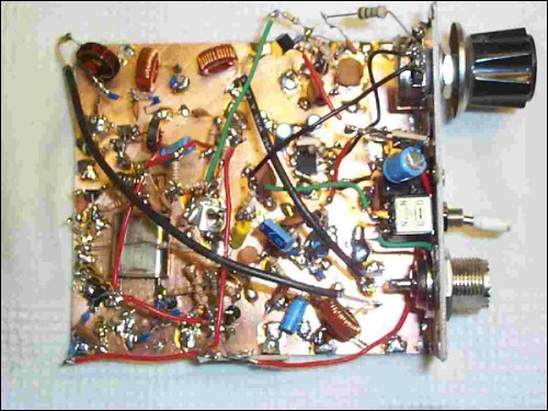
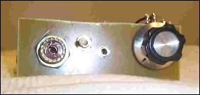
Very Ugly Construction


Conclusion
73 and have fun! , VE7BPO